Steward
分享是一種喜悅、更是一種幸福
 硬體
硬體
‐ LCM 4bits
‐ LCD Timing(VBPD、VFBD、VSPW、HBPD、HFPD、HSPW)
⊕ USB
‐ HID EndPoint
‐ Keyboard Scancode
‐ USB轉UART(8隻腳位的PL2303)
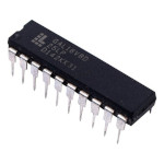 Lattice GAL22V10
‐ 簡要規格
‐ 開發板
‐ Build stcgal
‐ Afterburner Programmer
⊕ Assembly
‐ 開發環境
‐ LED
⊕ C/C++
‐ 開發環境
‐ LED
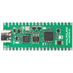 Lattice iCE40UP5K-SG48I (ICE40_FPGA_PICO)
‐ 簡要規格
‐ Schematic
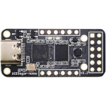 Lattice iCE40LP1K-CM36 (iCESugar-nano)
‐ 簡要規格
‐ 接腳
‐ 開發板
‐ 列印外殼
‐ Schematic
‐ Build ghdl
‐ Build yosys
‐ Build icestorm
‐ Build icesprog
‐ Build nextpnr-ice40
‐ Build ghdl-yosys-plugin
‐ 解決手機無法供電問題
‐ 解決No such file or directory: /usr/local/share/icebox/timings_hx1k.txt問題
‐ 如何透過icesprog燒錄
⊕ VHDL
‐ 開發環境
‐ LED
‐ Button
⊕ Verilog
‐ 開發環境
‐ LED
‐ Button
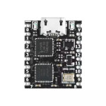 Lattice LCMXO2-1200HC-4SG32C
‐ 簡要規格
‐ 接腳
‐ 開發板
‐ Layout
‐ Schematic
‐ Build yosys
‐ Build prjtrellis
‐ Build openFPGALoader
‐ Build nextpnr-machxo2
‐ 安裝Lattice Diamond
‐ 如何透過yosys、nextpnr-machxo2編譯程式
‐ 解決ERROR: No such command: synth_machxo2問題
⊕ Lattice Diamond
⊕ Verilog
‐ LED
‐ Button
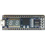 Lattice LCMXO2-4000HC-4MG132 (STEP-MXO2 V2)
‐ 簡要規格
‐ 接腳
‐ Layout
‐ 硬體改造
‐ 產品比較表
‐ Schematic
‐ Build yosys
‐ Build prjtrellis
‐ Build iverilog、vvp
‐ Build openFPGALoader
‐ Build nextpnr-machxo2
‐ 安裝Lattice Diamond
‐ 如何設定JTAG腳位成GPIO腳位
‐ 如何透過openFPGALoader燒錄
‐ 如何讓openFPGALoader支援STEP-MXO2開發板燒錄
‐ 解決無法進入JTAG模式的問題
‐ 解決ecppack無法產生*.jed問題
‐ 解決nextpnr-machxo2沒有支援LCMXO2-4000HC的問題
‐ 解決mcode undefined reference to __muldi3問題
‐ 解決ghdl.so: cannot open shared object file問題
⊕ Lattice Diamond
⊕ VHDL
‐ LED
‐ Button
⊕ VHDL
‐ LED
‐ Button
⊕ Verilog
‐ LED
‐ Button
‐ UART
‐ 如何使用iverilog、vvp、gtkwave
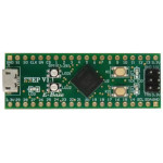 Lattice LCMXO2-1200HC-4MG132C (STEP-MXO2 V1.1)
‐ 簡要規格
‐ 接腳
‐ Layout
‐ Schematic
‐ Build yosys
‐ Build prjtrellis
‐ Build openFPGALoader
‐ Build nextpnr-machxo2
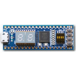 Altera 10M02SCM (STEP-MAX10 V1)
‐ 簡要規格
‐ 接腳
‐ Layout
‐ 型態轉換
‐ Schematic
‐ Delta Cycle
‐ 安裝Quartus Prime
‐ Build openFPGALoader
‐ 如何產生SVF、RBF檔案
‐ 如何透過openFPGALoader下載SVF檔案
‐ 如何使用Quartus Prime Command Line編譯專案
‐ 如何讓openFPGALoader支援10M02SCM153C8G燒錄
‐ 如何讓openFPGALoader支援STEP-MAX10開發板燒錄
‐ 解決USB-Blaster無法偵測到的問題(Linux)
‐ 解決JTAG init failed with: Unknown device with IDCODE問題
⊕ Quartus Prime
⊕ VHDL
‐ LED
‐ Button
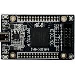 Xilinx XC6SLX16 (SMH-XS616N)
‐ 簡要規格
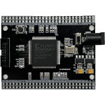 Xilinx XC3S50AN
‐ 簡要規格
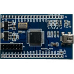 Xilinx XC2C32A (Xilinx Mini)
‐ 簡要規格
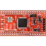 Xilinx XC2C64A (CoolRunner-II CPLD)
‐ 簡要規格
‐ 接腳
‐ 開發板
‐ Overview
‐ Schematic
‐ ALINX JTAG腳位
‐ 安裝Xilinx ISE 14.7
‐ Build openFPGALoader
‐ 如何透過openFPGALoader下載jed檔案
⊕ Xilinx ISE
⊕ Verilog
‐ LED
‐ Button
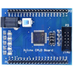 Xilinx XC9572XL (Xilinx FPGA CPLD)
‐ 簡要規格
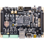 Xilinx ZYNQ7010 (AX7Z010)
‐ 簡要規格
‐ Layout
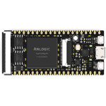 Anlogic EG4S20BG256 (Lichee Tang Primer)
‐ 簡要規格
‐ 接腳
‐ Layout
‐ Schematic
‐ Build yosys
‐ Install fusesoc
‐ Build openFPGALoader
‐ Patch Anlogic TD License
‐ 安裝Anlogic TD(Tang Dynasty)
‐ 如何透過yosys、td編譯程式
‐ 如何透過openFPGALoader下載bit檔案
‐ 解決libusb couldn't open USB device ... Permission denied問題
⊕ Verilog
‐ LED
‐ Button
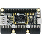 Gowin GW5A-LV25MG121C1/l0 (Lichee Tang Primer 25K)
‐ 簡要規格
‐ Layout
‐ Schematic
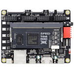 Gowin GW2A-LV18PG256C8/I7 (Lichee Tang Primer 20K)
‐ 簡要規格
‐ Layout
‐ Schematic
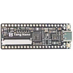 Gowin GW1NZ-LV1QN48C6/I5 (Lichee Tang Nano 1K)
‐ 簡要規格
‐ 接腳
‐ 產品比較表
‐ Layout
‐ Schematic
‐ Build yosys
‐ Build nextpnr-gowin
‐ Build openFPGALoader
⊕ VHDL
‐ LED
‐ Button
⊕ Verilog
‐ LED
‐ Button
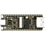 Gowin GW1NSR-LV4CQN48PC6/I5 (Lichee Tang Nano 4K)
‐ 簡要規格
‐ 接腳
‐ Schematic
‐ 安裝Gowin IDE
‐ 如何透過GOWIN Tcl編譯專案
‐ 如何透過openFPGALoader下載bit檔案
‐ 解決gowin_bba executable: GOWIN_BBA_EXECUTABLE-NOTFOUND問題
‐ Build yosys
‐ Build nextpnr-gowin
‐ Build openFPGALoader
‐ Build nextpnr-himbaechel
⊕ Gowin IDE
⊕ Verilog
‐ LED
‐ Button
⊕ VHDL
‐ LED
‐ Button
⊕ Verilog
‐ LED
‐ Button
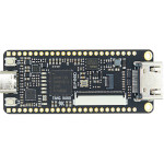 Gowin GW1NR-LV9QN88PC6/I5 (Lichee Tang Nano 9K)
‐ 簡要規格
‐ 接腳
‐ Layout
‐ Schematic
‐ Build yosys
‐ Build openFPGALoader
‐ Build nextpnr-himbaechel
⊕ VHDL
‐ LED
‐ Button
⊕ Verilog
‐ LED
‐ Button
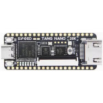 Gowin GW2AR-LV18QN88C8/I7 (Lichee Tang Nano 20K)
‐ 簡要規格
‐ 接腳
‐ Layout
‐ Schematic
‐ Build yosys
‐ Build openFPGALoader
‐ Build nextpnr-himbaechel
⊕ VHDL
‐ LED
‐ Button
⊕ Verilog
‐ LED
‐ Button
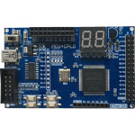 Altera EPM240T100C5N
‐ 簡要規格
‐ 接腳
‐ 開發環境
‐ 安裝Quartus Prime
‐ 解決USB-Blaster無法偵測到的問題(Linux)
⊕ VHDL
‐ LED
‐ Button
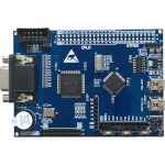 Altera EPM240T100C5N
‐ 簡要規格
‐ 接腳
‐ 開發環境
‐ 安裝Quartus Prime
‐ 解決USB-Blaster無法偵測到的問題(Linux)
⊕ VHDL
‐ LED
‐ Button
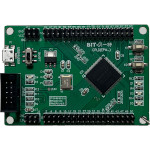 Altera EPM570T100C5N
‐ 簡要規格
 Altera EPM3064ATC44-10N
‐ 簡要規格
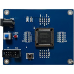 Altera EPM7032SLC44-10N (HY-101)
‐ 簡要規格
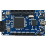 Altera EP4CE6E22C8N
‐ 簡要規格
‐ 接腳
‐ 開發環境
‐ 安裝Quartus Prime
‐ 解決USB-Blaster無法偵測到的問題(Linux)
⊕ VHDL
‐ LED
‐ Button
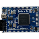 Altera EP4CE6E22C8N
‐ 簡要規格
‐ 接腳
‐ 開發環境
‐ 安裝Quartus Prime
‐ 解決USB-Blaster無法偵測到的問題(Linux)
⊕ VHDL
‐ LED
‐ Button
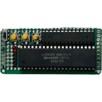 SHARP LH0080A
‐ 簡要規格
‐ 腳位
‐ 開發板
⊕ STC15F204EA
‐ 開發環境
‐ LED
‐ Button
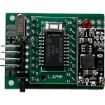 NXP MC68HC908JB8
‐ 簡要規格
‐ 腳位
‐ 開發板
‐ 中斷表
‐ bl08.c
‐ Memory Map
‐ Monitor Mode
⊕ Assembly
‐ 開發環境
‐ LED
‐ Button
 STCmicro STC12C5A60S2
‐ 簡要規格
 STCmicro STC15W104
‐ 簡要規格
‐ 腳位
‐ 比較表
‐ 暫存器
‐ 指令集
‐ 開發板
‐ OPCode
‐ 中斷向量
⊕ Assembly
‐ 開發環境
‐ LED
‐ INT1
‐ Clock
‐ Button
‐ EEPROM
‐ Timer2
‐ Watchdog
‐ Software Reset
‐ Power-Down、Idle
‐ UART TX(57600bps)
‐ UART RX(57600bps)
‐ Timer0(Timer、Mode0)
‐ Timer0(Timer、Mode1)
‐ Timer0(Timer、Mode2)
‐ Timer0(Timer、Mode3)
⊕ W25Q64
‐ Read JEDEC ID
‐ Erase、Write、Read
 STCmicro STC15W204S
‐ 簡要規格
‐ 腳位
‐ 比較表
‐ 開發板
‐ Build stcgal
‐ 使用Windows STC-ISP燒録程式
⊕ Assembly
‐ 開發環境
‐ Show PNG
‐ 0.96" OLED 128x64 SSD1306
 STCmicro STC15W408AS
‐ 簡要規格
‐ 開發板
⊕ C/C++
‐ 開發環境
‐ LED
‐ Button
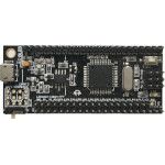 STCmicro STC15W4K56S4
‐ 簡要規格
‐ stc15w4k56s4.h
⊕ C/C++
‐ 1.30" TFT 240x240 ST7789V
‐ 1.45" TFT 240x240 ST7789V
‐ 1.54" IPS 240x240 ST7789V
‐ 2.00" IPS 320x240 JBT6K71-AS
‐ 2.80" IPS 320x240 S6D04M0X21
‐ 3.50" IPS 320x480 ILI9488
‐ 0.91" OLED 128x32 SSD1306
‐ 0.96" OLED 128x64 SSD1306
‐ 1.50" OLED 128x128 SSD1351
‐ 1.54" ePaper 152x152 Black-Yellow
‐ 1.54" ePaper 200x200 Black-Red
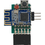 TI CC2540
‐ 簡要規格
‐ 腳位
‐ 中斷表
‐ 開發板
‐ Build cc-tool
‐ 解決Configure: error: invalid value: boost_major_version問題
‐ 解決Error occured: libusb_control_transfer (out) failed, Pipe error問題
⊕ Assembly
‐ 開發環境
‐ LED
‐ Button
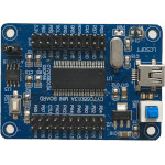 Cypress CY7C68013
‐ 簡要規格
‐ 開發板
‐ 如何抹除EEPROM
‐ 如何燒錄HEX到RAM
‐ 如何燒錄HEX到EEPROM
‐ 解決SDCC xdata syntax error問題
‐ Build FXLoad
‐ build CycFX2Prog
⊕ Assembly
‐ 開發環境
‐ LED
‐ Button
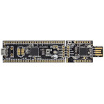 Cypress CY8C5888LTI-LP097 (CY8CKIT-059)
‐ 簡要規格
‐ 接腳
‐ Schematic
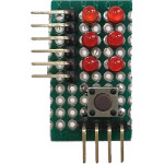 Microchip PIC10F200
‐ 簡要規格
‐ 比較表
‐ 指令集
‐ 記憶體
‐ 開發板
‐ 如何修改TRIS暫存器
‐ 如何修改OPTION暫存器
⊕ Assembly
‐ 開發環境
‐ LED
‐ Button
‐ Watchdog
‐ 3根GPIO驅動6顆LED
‐ UART TX(9600bps)
‐ Wake-up on Pin Change
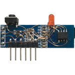 Microchip PIC12F1822
‐ 簡要規格
‐ 腳位
‐ 比較表
‐ 記憶體
‐ 開發板
‐ 指令集
‐ PICKit3腳位
‐ 解決SDCC cannot generate code for target pic14問題
‐ 解決Warning[202] Argument out of range. Least significant bits used問題
⊕ Assembly
‐ 開發環境
‐ LED
‐ Button
‐ EEPROM
‐ Watchdog
‐ Oscillator
‐ Flash Memory
‐ Interrupt On Change(IOC)
‐ 0.91" OLED 128x32 SSD1306
‐ 0.91" OLED 128x32 SSD1306(顯示字串)
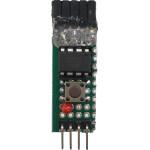 Microchip ATtiny13
‐ 簡要規格
‐ 腳位
‐ 中斷表
‐ 開發板
‐ 如何透過avrdude更新FUSE
‐ 如何透過avrdude更新EEPROM
‐ 解決avrdude: error: program enable: target doesn't answer問題
⊕ Assembly
‐ 開發環境
‐ LED
‐ Sleep
‐ Timer
‐ Button
‐ EEPROM
‐ Watchdog
‐ UART TX(9600bps)
‐ Compare Match Output
‐ Pin Change Interrupt
‐ Self-Programming Flash
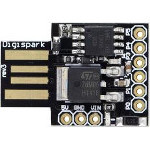 Microchip ATtiny85
‐ 簡要規格
‐ 開發板
‐ 接腳
‐ Schematic
⊕ C/C++
‐ 開發環境
‐ LED
‐ Button
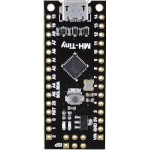 Microchip ATtiny88 (MH-Tiny)
‐ 簡要規格
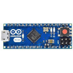 Microchip ATmega32U4 (Arduino Micro)
‐ 簡要規格
‐ 接腳
‐ Schematic
⊕ Arduino
‐ 開發環境
‐ LED
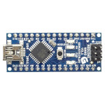 Microchip ATmega328 (Arduino Nano)
‐ 簡要規格
‐ 接腳
‐ Schematic
⊕ Arduino
‐ 開發環境
‐ LED
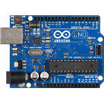 Microchip ATmega328P (Arduino Uno)
‐ 簡要規格
‐ 接腳
‐ Schematic
‐ 如何更新Arduino Micro Bootloader
‐ 如何更新KTduino Nano(CH340G) Bootloader
‐ 如何修復USB ISP(zhifengsoft)無法使用avrdude的問題
⊕ Arduino
‐ 開發環境
‐ LED
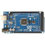 Microchip ATmega2560 (Arduino Mega)
‐ 簡要規格
‐ 接腳
‐ Schematic
‐ 如何提高analogRead()讀取速率
⊕ Arduino
‐ 開發環境
‐ LED
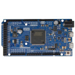 Microchip ATSAM3X8E (Arduino Due)
‐ 簡要規格
‐ 接腳
‐ Schematic
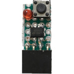 STMicroelectronics STM8S001
‐ 簡要規格
‐ 腳位
‐ 中斷表
‐ 指令集
‐ 暫存器
‐ 記憶體
‐ 開發板
‐ 解決stm8flash ... Tries exceeded問題
⊕ Assembly
‐ 開發環境
‐ LED
‐ Button
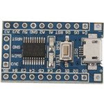 STMicroelectronics STM8S103
‐ 簡要規格
‐ 接腳
‐ 開發板
‐ Layout
‐ Schematic
⊕ Assembly
‐ 開發環境
‐ LED
‐ UART
‐ Flash
‐ Button
‐ Timer1
‐ Timer2
‐ Timer4
‐ EEPROM
‐ Auto-wakeup(AWU)
‐ Window watchdog(WWDG)
‐ Independent watchdog(IWDG)
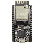 Espressif ESP-32S (NodeMCU-32)
‐ 簡要規格
‐ 接腳
‐ 如何使用Serial
‐ Additional Boards Manager URLs
‐ 解決Could not open /dev/ttyUSB0問題
⊕ C/C++
‐ Read MAC Address
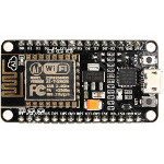 Espressif ESP8266MOD (NodeMCU ESP8266)
‐ 簡要規格
‐ 接腳
‐ Schematic
‐ Build esp-idf
⊕ Arduino
‐ 開發環境
‐ LED
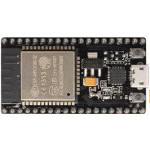 Espressif ESP-WROOM-32 (NodeMCU ESP-WROOM-32)
‐ 簡要規格
‐ 接腳
‐ Schematic
‐ Build esp-idf
‐ 解決Compilation error: MPU6050 has no member named begin問題
⊕ Arduino
‐ 開發環境
‐ LED
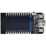 Espressif ESP32-D0WDQ6 (TTGO)
‐ 簡要規格
‐ 接腳
‐ Schematic
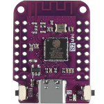 Espressif ESP32-S2F (S2 Mini)
‐ 簡要規格
‐ 接腳
‐ Schematic
⊕ Arduino
‐ 開發環境
‐ LED
‐ Button
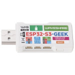 Espressif ESP32-S3R2 (ESP32-S3-GEEK)
‐ 簡要規格
‐ 接腳
‐ Layout
‐ Schematic
⊕ Arduino
‐ 開發環境
‐ LCD
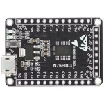 Nuvoton N76E003 (MCU-E003)
‐ 簡要規格
‐ 腳位
‐ 開發板
‐ SFR
‐ Data Memory
‐ Block Diagram
‐ Program Memory
⊕ C/C++
‐ 開發環境
‐ LED
‐ Button
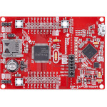 TI MSP430FR5994 (MSP-EXP430FR5994)
‐ 簡要規格
‐ 腳位
‐ 開發板
‐ 產品比較表
‐ Schematic
‐ Block Diagram
‐ Operating Modes
⊕ C/C++
‐ 開發環境
‐ LED
‐ Button
 Silicon Labs C8051F300 (WCMCU-8051)
‐ 簡要規格
‐ 開發板
‐ Build ec2-new
⊕ C/C++
‐ 開發環境
‐ LED
‐ Button
 LogicGreen LGT8F328P (MiniEVB)
‐ 簡要規格
 ARM
ARM
‐ GIC Table
‐ Carry Flag
‐ NEON Register
‐ ldmia sp!, {pc}^
‐ Conditional Execution
‐ push、pop、stmfd、ldmfd
‐ ldr pc, _irq、ldr pc, =_irq、adr pc, _irq
 Samsung S3C44B0X
‐ 簡要規格
‐ 腳位
‐ 接腳
‐ 開發板
‐ JTAG腳位
‐ 如何使用JLinkExe下載程式
‐ 如何使用J-Link GDB Server和IDA Pro除錯程式
‐ 解決SST39VF1601前32KB無法抹除的問題
⊕ Assembly
‐ 開發環境
‐ LED
‐ Button
‐ Phase Locked Loop(PLL)
 Samsung S3C2416
‐ 簡要規格
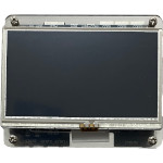 Samsung S3C2440 (JZ2440)
‐ 簡要規格
‐ 電路圖
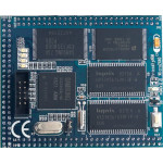 Samsung S3C2440 (Micro2440)
‐ 簡要規格
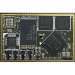 Samsung S3C6410
‐ 簡要規格
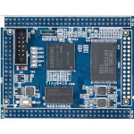 Samsung S3C6410 (Tiny6410)
‐ 簡要規格
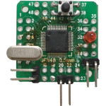 NXP LPC2103
‐ 簡要規格
‐ 腳位
‐ 開發板
‐ 記憶體
‐ 中斷表
‐ 如何進入ISP模式
‐ 如何使用lpc21isp燒錄
‐ Build lpc21isp
‐ Enable Interrupt
‐ Interrupt Return Address
⊕ Assembly
‐ 開發環境
‐ LED
‐ UART
‐ Button
‐ Timer0
‐ Timer1
‐ Timer2
‐ Timer3
‐ EINT1(FIQ)
‐ EINT1(IRQ)
‐ EINT1(Vector IRQ)
‐ EINT1(Non-vectored IRQ)
‐ Power-down
‐ WatchDog Timer(WDT)
‐ Phase Locked Loop(PLL)
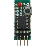 NXP LPC810
‐ 簡要規格
‐ 開發板
‐ 中斷表
‐ Memory Map
⊕ Assembly
‐ 開發環境
‐ LED
‐ Button
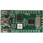 NXP LPC812
‐ 簡要規格
‐ 中斷表
‐ Build lpc21isp
‐ 如何使用lpc21isp燒錄
⊕ Assembly
‐ 開發環境
‐ LED
‐ Button
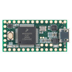 NXP MK20DX256 (Teensy 3.2)
‐ 簡要規格
‐ 接腳
‐ 開發板
‐ 中斷表
‐ 開機流程
‐ Schematic
‐ Memory Map
‐ Build teensy_loader_cli
‐ 如何透過teensy_loader_cli燒錄程式
⊕ Assembly
‐ 開發環境
‐ LED
‐ Button
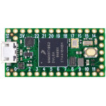 NXP RT1062 (Teensy 4.0)
‐ 簡要規格
‐ 接腳
‐ 開發板
‐ 中斷表
‐ Schematic
‐ Build teensy_loader_cli
‐ 如何透過teensy_loader_cli燒錄程式
⊕ Assembly
‐ 開發環境
‐ LED
‐ Button
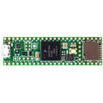 NXP RT1062 (Teensy 4.1)
‐ 簡要規格
‐ 接腳
‐ Schematic
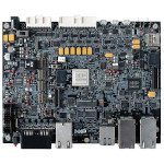 NXP S32G399 (S32G-VNP-RDB2)
‐ 簡要規格
‐ Build U-Boot
‐ Build Kernel
‐ 解決ntpd -gq resulted in error問題
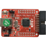 Microchip AT91SAM7S64
‐ 簡要規格
‐ 腳位
‐ 中斷表
‐ 開發板
‐ 比較表
‐ 記憶體
‐ 如何使用SAM-BA燒錄
‐ 為何VDDOUT沒有輸出1.8V
‐ Peripheral Identifiers
⊕ Assembly
‐ 開發環境
‐ LED
‐ Button
‐ Phase Locked Loop(PLL)
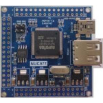 Nuvoton NUC977
‐ 簡要規格
‐ 比較表
‐ 架構圖
‐ 中斷表
‐ 記憶體
‐ 開發板
‐ 排針腳位
‐ 開機選項
‐ Flash SPI
‐ Flash NAND
‐ Build U-Boot
‐ Build Kernel
‐ Build NuWriter
‐ 解決unknown type name sha1_context問題
⊕ Assembly
‐ 開發環境
‐ LED
‐ UART0
‐ Timer0
‐ Timer1
‐ Timer2
‐ Timer3
‐ Timer4
‐ Button
‐ GPIO(FIQ)
‐ GPIO(IRQ)
‐ Watchdog Timer(WDT)
‐ Phase Locked Loop(PLL)
‐ Windowed Watchdog Timer(WWDT)
‐ Enhance Timer0 Controller(ETMR0)
‐ Enhance Timer1 Controller(ETMR1)
‐ Enhance Timer2 Controller(ETMR2)
‐ Enhance Timer3 Controller(ETMR3)
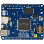 Nuvoton NUC972
‐ 簡要規格
‐ 比較表
‐ 架構圖
‐ 中斷表
‐ 記憶體
‐ 開發板
‐ 排針腳位
‐ 開機選項
‐ 如何開啟Framebuffer Console
⊕ Assembly
‐ 開發環境
‐ LED
‐ Timer0
‐ Timer1
‐ Timer2
‐ Timer3
‐ Timer4
‐ Button
‐ GPIO(FIQ)
‐ GPIO(IRQ)
‐ Watchdog Timer(WDT)
‐ Phase Locked Loop(PLL)
‐ Windowed Watchdog Timer(WWDT)
‐ Enhance Timer0 Controller(ETMR0)
‐ Enhance Timer1 Controller(ETMR1)
‐ Enhance Timer2 Controller(ETMR2)
‐ Enhance Timer3 Controller(ETMR3)
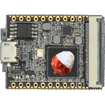 Allwinner F1C100S (荔枝派Nano)
‐ 簡要規格
‐ 開發板
‐ 中斷表
‐ mksunxi.c
‐ Schematic
‐ Memory Map
‐ 製作JTAG連接器
‐ 如何超頻到2.0GHz
‐ BROM ffff0000.s
‐ BROM ffff4000.s
‐ Build sunxi-tools
‐ 如何透過JLink初始化DRAM
‐ 為何程式無法從MicroSD啟動
‐ 如何在MicroSD啟動下改成SPI啟動
‐ 如何將U-Boot的輸出訊息轉到UART1
‐ 如何使用J-Link GDB Server和IDA Pro除錯程式
⊕ Assembly
‐ 開發環境
‐ LED
‐ CCU
‐ INTC
‐ DRAM
‐ UART
‐ SDMMC
‐ KEYADC
‐ Timer0
‐ Timer1
‐ Timer2
‐ TWI(I2C)
‐ Watchdog
‐ SPI(NOR Flash)
⊕ C/C++
‐ 溫度量測
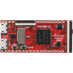 Allwinner F1C200S (Tiny200)
‐ 簡要規格
‐ 接腳
‐ 開發板
‐ 記憶體
‐ 中斷表
‐ Schematic
‐ 製作JTAG連接器
‐ 如何超頻到2.0GHz
‐ 如何使用J-Link GDB Server和IDA Pro除錯程式
⊕ Assembly
‐ 開發環境
‐ LED
‐ CCU
‐ INTC
‐ DRAM
‐ UART
‐ SDMMC
‐ Button
‐ Timer0
‐ Timer1
‐ Timer2
‐ TWI(I2C)
‐ Watchdog
‐ SPI(NAND Flash)
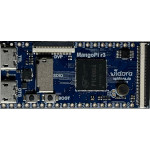 Allwinner F1C500S (MangoPi R3)
‐ 簡要規格
‐ 接腳
‐ Schematic
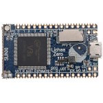 Allwinner V3S (Lichee Pi Zero)
‐ 簡要規格
‐ 接腳
‐ 開發板
‐ Schematic
‐ mksunxi.c
‐ Memory Map
‐ Build U-Boot
‐ Build sunxi-tools
‐ Build Kernel 6.3.5
‐ Build Kernel 4.10.15
‐ 如何將uboot的輸出訊息轉到UART1
⊕ Assembly
‐ 開發環境
‐ LED
‐ CCU
‐ GIC
‐ UART
‐ Button
‐ Timer0
‐ Timer1
‐ Timer2
‐ Watchdog
‐ HS Timer0
‐ HS Timer1
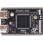 Allwinner T113-S3 (MangoPi MQ-R)
‐ 簡要規格
‐ 接腳
‐ 腳位
‐ 開發板
‐ 中斷表
‐ Schematic
‐ mksunxi.c
‐ Build XBoot
‐ Build AWBoot
‐ 如何從Micro SD啟動
‐ Build Kernel 6.0.1
‐ 分析XBoot GT911無法觸發中斷的原因
⊕ Assembly
‐ 開發環境
‐ LED
‐ Button
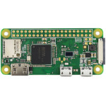 Broadcom BCM2835 (Raspberry Pi Zero)
‐ 簡要規格
‐ 接腳
‐ 開發板
‐ 中斷表
‐ 開機順序
‐ Peripheral Address
⊕ Assembly
‐ 開發環境
‐ LED
‐ Button
⊕ QEMU
‐ 安裝系統
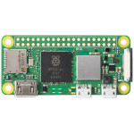 Broadcom BCM2835 (Raspberry Pi Zero W)
‐ 簡要規格
‐ 接腳
‐ Layout
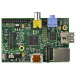 Broadcom BCM2835 (Raspberry Pi)
‐ 簡要規格
‐ 接腳
‐ 開發板
‐ 中斷表
‐ 開機順序
‐ P5 Head
‐ Peripheral Address
⊕ Assembly
‐ 開發環境
‐ LED
‐ Button
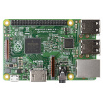 Broadcom BCM2836 (Raspberry Pi 2)
‐ 簡要規格
‐ 接腳
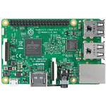 Broadcom BCM2837 (Raspberry Pi 3)
‐ 簡要規格
‐ 接腳
⊕ Bookworm
‐ 安裝系統
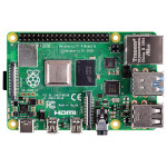 Broadcom BCM2711 (Raspberry Pi 4)
‐ 簡要規格
‐ 接腳
⊕ Bookworm
‐ 安裝系統
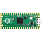 Raspberry Pi RP2040 (Pico)
‐ 簡要規格
‐ 接腳
‐ 腳位
‐ 開發板
‐ Bus
‐ GPIO
‐ Model
‐ Layout
‐ Overview
‐ Schematic
‐ Build pico-sdk
‐ Build picotool
‐ Build pico-extras
⊕ Assembly
‐ 開發環境
‐ LED
⊕ C/C++
‐ 開發環境
‐ LED
‐ Button
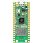 Raspberry Pi RP2040 (Pico W)
‐ 簡要規格
‐ 接腳
‐ Schematic
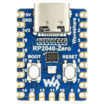 Raspberry Pi RP2040 (Zero)
‐ 簡要規格
‐ 接腳
‐ Layout
‐ Schematic
‐ Build pico-sdk
‐ Build picotool
‐ Build pico-extras
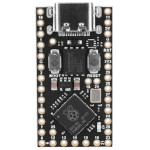 Raspberry Pi RP2040 (ProMicro)
‐ 簡要規格
‐ 接腳
‐ Build pico-sdk
‐ Build picotool
‐ Build pico-extras
⊕ Assembly
‐ 開發環境
‐ LED
 Raspberry Pi RP2040 (LCd 0.96)
‐ 簡要規格
‐ 接腳
‐ Layout
‐ Schematic
‐ Build pico-sdk
‐ Build picotool
‐ Build pico-extras
⊕ Assembly
‐ 開發環境
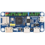 Raspberry Pi RP2350 (RP2350-PiZero)
‐ 簡要規格
‐ 腳位
‐ Layout
‐ Schematic
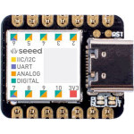 Microchip ATSAMD21G18 (Seeed Studio XIAO SAMD21)
‐ 簡要規格
‐ 腳位
‐ 接腳
‐ 開發板
‐ 中斷表
‐ Schematic
‐ Memory Map
‐ Input Configuration
⊕ Assembly
‐ 開發環境
‐ LED
‐ Button
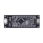 Microchip ATSAMD21G18 (SAMD21 M0-Mini)
‐ 簡要規格
‐ 接腳
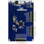 Microchip ATSAMD21J18 (SAMD21-XPro)
‐ 簡要規格
‐ Layout
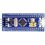 STMicroelectronics STM32F103
‐ 簡要規格
‐ 接腳
‐ 開發板
‐ 中斷表
‐ Memory Map
‐ Pull-up/Pull-Down
‐ 如何在Debian x64上Debug STM32
‐ 如何透過UART燒錄程式(Flash Loader)
‐ 如何透過ST-LINK V2燒錄程式(OpenOCD)
‐ 解決Section .plt LMA overlaps section .dynamic LMA問題
‐ 解決Cannot insert breakpoint 1. Cannot access memory at address問題
‐ 解決Error: jtag status contains invalid mode value - communication failure問題
⊕ Assembly
‐ 開發環境
‐ LED
‐ UART
‐ Button
‐ I/O Toggle 21MHz
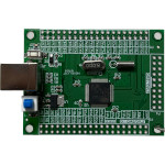 STMicroelectronics STM32F103 (Guava)
‐ 簡要規格
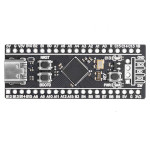 STMicroelectronics STM32F401 (WeAct Black Pill)
‐ 簡要規格
‐ 接腳
‐ Schematic
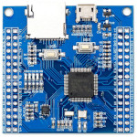 STMicroelectronics STM32F405
‐ 簡要規格
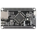 STMicroelectronics STM32F407
‐ 簡要規格
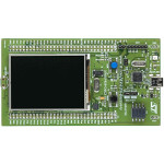 STMicroelectronics STM32F429 (STM32F429I-DISC1)
‐ 簡要規格
‐ 接腳
‐ 中斷表
‐ Memory Map
‐ GPIO Configuration
⊕ Assembly
‐ 開發環境
‐ LED
‐ Button
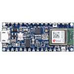 Nordic Semiconductor nRF52840 (Arduino Nano 33 BLE)
‐ 簡要規格
‐ 接腳
‐ 電路圖
‐ 如何使用Serial
‐ 如何防止IP5306自動斷電
‐ 如何透過ST-LINK V2燒錄程式(OpenOCD)
‐ 解決NRF24L01只能傳送不能接收問題
⊕ C/C++
‐ 開發環境
‐ LED
 Nordic Semiconductor nRF52840 (ProMicro NRF52840)
‐ 簡要規格
‐ 接腳
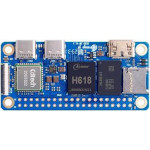 Allwinner H618 (Orange Pi Zero 2W)
‐ 簡要規格
‐ 接腳
‐ Layout
‐ Schematic
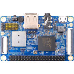 RDA RDA8810PL (Orange Pi 2G-IoT)
‐ 簡要規格
‐ Create UBI.img
‐ Flash Image(NAND)
‐ Build All
‐ Build U-Boot
‐ LCD Pin
‐ Head Pin
‐ Panel Pin
‐ Camera Pin
‐ DIP Switch
‐ 如何輸出詳細的Kernel訊息
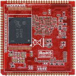 TI AM3352 (CM335H)
‐ 簡要規格
‐ 接腳
‐ 解決顯示在LCD上面的圖形會緩慢移動的問題
‐ 解決Frame Synchronization Lost Enabled Interrupt問題
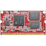 TI AM3352 (CM335X)
‐ 簡要規格
‐ 接腳
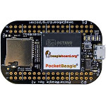 TI AM3358 (PocketBeagle)
‐ 簡要規格
‐ 接腳
‐ Layout
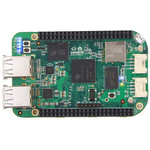 TI AM3358 (SeeedStudio BeagleBone Green Wireless)
‐ 簡要規格
‐ 接腳
‐ PinMux
‐ 為何LCD Ping-Pongs Buffer顯示會閃爍
‐ 解決LIDD DMA在中斷後無法啟動的問題
‐ 解決Unhandled fault: ... non-linefetch (0x1028)問題
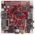 TI DM3730 (BeagleBoard-XM)
‐ 簡要規格
‐ GPIO
‐ LED位置
‐ 焊接UART
‐ Schematic
‐ Interconnect
‐ L4 Interconnect
‐ 如何製作可開機的MicroSD
⊕ Assembly
‐ 開發環境
‐ LED
‐ Button
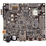 TI OMAP4460 (PandaBoard ES)
‐ 簡要規格
‐ Layout
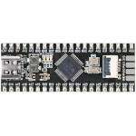 TI MSPM0G3507
‐ 簡要規格
‐ 腳位
‐ 接腳
‐ MSPM0系列
‐ Layout
‐ Schematic
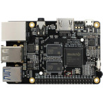 Rockchip RK3328 (ROC-RK3328-CC)
‐ 簡要規格
‐ 接腳
‐ Layout
‐ Schematic
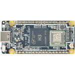 Allwinner H3 (NanoPi Duo2)
‐ 簡要規格
‐ 接腳
‐ Layout
‐ mksunxi.c
‐ Schematic
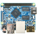 Allwinner H3 (NanoPi M1)
‐ 簡要規格
‐ 接腳
‐ Layout
‐ mksunxi.c
‐ Schematic
‐ 如何初始化R_GPIO
⊕ Assembly
‐ 開發環境
‐ LED
‐ Button
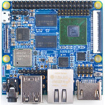 Samsung S5P6818 (NanoPi M3)
‐ 簡要規格
‐ 接腳
‐ Layout
‐ Schematic
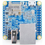 Allwinner H3 (NanoPi NEO)
‐ 簡要規格
‐ 接腳
‐ Layout
‐ Schematic
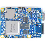 Rockchip RK3399 (NanoPi NEO4)
‐ 簡要規格
‐ Layout
‐ Schematic
‐ Build xrock
⊕ Assembly
‐ 開發環境
‐ LED
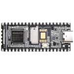 RockChip RV1103 (Luckfox Pico)
‐ 簡要規格
‐ 接腳
‐ Layout
‐ Schematic
‐ Build xrock
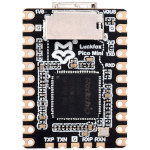 RockChip RV1103 (Luckfox Pico Mini B)
‐ 簡要規格
‐ 接腳
‐ 開發板
‐ Layout
‐ Schematic
‐ Build xrock
⊕ Assembly
‐ 開發環境
‐ LED
‐ Button
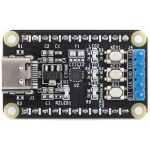 Puya PY32F002BF15U6TR
‐ 簡要規格
 MIPS
MIPS
‐ Register
‐ Quick Instruction Set
‐ Memory Map(kuseg、kseg0、kseg1、kseg2)
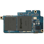 Ingenic JZ4775 (Newton)
‐ 簡要規格
‐ Layout
‐ 開發板
‐ UART輸出
‐ Flash Image
‐ Build U-Boot
‐ Build Kernel
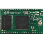 Atheros AR9331 (JS9331)
‐ 簡要規格
‐ 腳位
‐ 開發板
‐ UART輸出
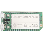 MediaTek MT7688 (LinkIt Smart 7688)
‐ 簡要規格
‐ 接腳
‐ 開發板
‐ Layout
‐ Build U-Boot
‐ Build OpenWRT
‐ Build Kernel 3.18.44
‐ 如何產生LinkIt7688-squashfs-sysupgrade.bin
‐ 解決mt_wifi.ko_3.18.45 No such file or directory問題
‐ 解決node_modules/mraa/* No such file or directory問題
‐ 解決squashfs: SQUASHFS error: Filesystem uses "zlib" compression問題
⊕ Assembly
‐ 開發環境
‐ LED
‐ Button
‐ CPU Clock
‐ Timer0(Polling)
‐ Timer1(Polling)
‐ Watchdog(Polling)
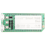 MediaTek MT7688 (LinkIt Smart 7688 Duo)
‐ 簡要規格
‐ 接腳
‐ 開發板
‐ 中斷表
‐ Layout
‐ Memory Map
‐ Clock Diagram
‐ 載入SPI的執行位址
‐ Build Kernel 5.4.83
‐ Branch、Jump指令的差異
‐ 解決can't open /dev/null /dev/console: No such file or directory問題
⊕ Assembly
‐ 開發環境
‐ LED
‐ Button
‐ CPU Clock
‐ Timer0(Polling)
‐ Timer1(Polling)
‐ Watchdog(Polling)
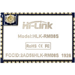 MediaTek MT7688 (HLK-RM08S)
‐ 簡要規格
‐ 腳位
‐ 開發板
‐ 中斷表
‐ MT7688版本
‐ Layout
‐ Memory Map
‐ Clock Diagram
⊕ Assembly
‐ 開發環境
‐ LED
‐ Button
 Microchip PIC32MX795 (UBW32)
‐ 簡要規格
‐ Schematic
 RISC-V
‐ Register
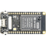 Bouffalo Lab BL808 (Sipeed M1s Dock)
‐ 簡要規格
‐ 接腳
‐ 開發板
‐ Schematic
‐ Boot Mode
⊕ Assembly
‐ 開發環境
‐ LED
‐ Button
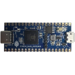 Bouffalo Lab BL808 (Ox64)
‐ 簡要規格
‐ 接腳
‐ Schematic
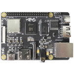 Allwinner D1-H (Sipeed Nezha)
‐ 簡要規格
‐ 開發板
‐ Schematic
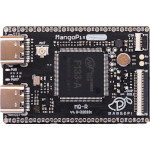 Allwinner F133-A (MangoPi MQ-R)
‐ 簡要規格
‐ 接腳
‐ 開發板
‐ Schematic
‐ Build XBoot
‐ gen_checksum.py
⊕ Assembly
‐ 開發環境
‐ LED
‐ Button
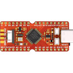 GigaDevice GD32VF103 (Sipeed Longan Nano)
‐ 簡要規格
‐ 腳位
‐ 接腳
‐ 開發板
‐ Schematic
‐ Memory Map
⊕ Assembly
‐ 開發環境
‐ LED
‐ Button
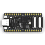 Kendryte K210 (Sipeed Maix Bit)
‐ 簡要規格
‐ 接腳
‐ 如何使用kflash燒錄
‐ Build SDK
‐ OpenOCD
‐ OpenOCD + GDB
⊕ C/C++
‐ Hello, world!
‐ LED
‐ Button
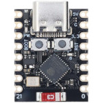 Espressif ESP32-C3 (Super Mini)
‐ 簡要規格
‐ 接腳
‐ Layout
‐ Schematic
‐ 如何安裝Arduino CLI
⊕ Arduino
‐ LED
‐ Button
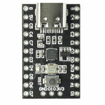 WCH CH32V003 (nanoCH32V003)
‐ 簡要規格
‐ 腳位
‐ 開發板
‐ Daigram
‐ Schematic
‐ Memory Map
‐ Architecture
‐ 解決Probe is not attached to an MCU, or debug is not enabled問題
⊕ Assembly
‐ 開發環境
‐ LED
‐ Button
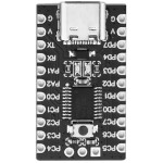 WCH CH32V003
‐ 簡要規格
‐ 腳位
‐ 開發板
‐ Daigram
‐ Schematic
‐ Memory Map
‐ Architecture
⊕ Assembly
‐ 開發環境
‐ LED
‐ Button
 WCH CH32V305 (WCH-LinkE)
‐ 簡要規格
‐ Schematic
‐ 如何透過WCH-LinkUtility回復韌體
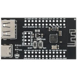 WCH CH582M
‐ 簡要規格
 Intel
Intel
⊕ 80386
‐ 指令集
‐ Jump Flags
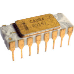 Intel 4004
‐ 簡要規格
‐ 腳位
‐ 指令集
‐ Register
‐ Architecture
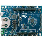 Intel Quark D2000
‐ 簡要規格
‐ OpenOCD
‐ OpenOCD + GDB
‐ Build QMSI
‐ Build Bootloader