Play Station
Video
Ref. http://www.raphnet.net/electronique/psx_adaptor/Playstation.txt
感謝Joshua Walker整理了如此詳細的資料,並且願意分享出來,讓對PS1模擬器感興趣的開發者,得以有一個更好的參考資料,司徒基於該資料,重新分段整理,也希望未來的PS1模擬器,可以開發的越來越好。
Overview
The Graphics Processing Unit (GPU)
The Graphics Transformation Engine (GTE)
The Motion Decoder (MDEC)
Overview
The GPU is the unit responsible for the graphical output of the PSX. It handles display and drawing of all graphics. It has the control over an 1MB frame buffer, which at 16 bits per pixel gives you a maximum “surface” of 1024x512 resolution. It also contains a 2Kb texture cache for increased speed. The display can be set for 15-bit color or 24-bit color.
Because the PSX also totally lacks an FPU. A second co-processor has been added called the Geometry Transformation Engine or GTE. The GTE is the heart of all 3d calculations on the PSX. The GTE can perform vector and matrix operations, perspective transformation, color equations and the like. It is much faster than the CPU on these operations. It is mounted as the second co-processor (Cop2) and as such takes up no physical address space in the PSX. The GTE is covered later in the document.
The Graphics Processing Unit (GPU)
As stated before the GPU is responsible for graphical output. It has at it’s disposal a 1 MB frame buffer and registers to access it. The frame buffer it totally inaccessible to the CPU, meaning that it doesn’t reside in addressable memory. The only way to access it is through the GPU. The GPU is able to take “commands” from the CPU, or via DMA to place objects on the frame buffer to be displayed. Communication is handled through a command and data port. It has a 64 byte command FIFO buffer, which can hold up to 3 commands and is connected to a DMA channel for transfer of image data and linked command lists (channel 2) and a DMA channel for reverse clearing an Ordering Table (channel 6).
Communication and Ordering Tables (OT)
All data regarding drawing and drawing environment are sent as packets to the GPU. Each packet tells the GPU how and where to draw one primitive, or it sets one of the drawing environment parameters. The display environment is set up through single word commands using the control port of the GPU.
Packets can be forwarded word by word through the data port of the GPU, or more efficiently for large numbers of packets through DMA. A special DMA mode was created for this so large numbers of packets can be sent and managed easily. In this mode a list of packets is sent, where each entry in the list contains a header which is one word containing the address of the next entry and the size of the packet and the packet itself. A result of this is that the packets do not need to be stored sequentially. This makes it possible to easily control the order in which packets get processed. The GPU processes the packets it gets in the order they are offered. So the first entry in the list also gets drawn first. To insert a packet into the middle of the list simply find the packet after which needs it to be processed, replace the address in that packet with the address of the new packet, and let that point to the address that was replaced.
To aid in finding a location in the list, the Ordering Table was invented. At first this is basically a linked list with entries of packet size 0, so it's a list of only list entry headers, where each entry points to to the next entry. Then as primitives are generated by your program you can then add them to the table at a certain index. Just read the address in the table entry and replace it with the address of the new packet and store the address from the table in the packet. When all packets are generated drawing will just require passing the address of the first list entry to the DMA and the packets will get drawn in the order you entered the packets to the table. Packets entered at a higher table index will get drawn after those entered at a lower table index. Packets entered at the same index will get drawn in the order they were entered, the last one first.
In 3d drawing it's most common that you want the primitives with the highest Z value to be drawn first, so it would be nice if the table would be drawn the other way around, so the Z value can be used as index. This is a simple thing, just make a table of which each entry points to the previous entry, and start the DMA with the address of the last table entry. To assist you in making such a table, a special DMA channel is available which creates it for you.
The Frame Buffer
The frame buffer is the memory which stores all graphic data which the GPU can access and manipulate, while drawing and displaying an image . The memory is under the GPU and cannot be accessed by the CPU directly. It is operated solely by the GPU. The frame buffer has a size of 1 MB and is treated as a space of 1024 pixels wide and 512 pixels high. Each "pixel" has the size of one word (16 bit). It is not treated linearly like usual memory, but is accessed through coordinates, with an upper left corner of (0,0) and a lower right corner of (1023,511).
When data is displayed from the frame buffer, a rectangular area is read from the specified coordinate within this memory. The size of this area can be chosen from several hardware defined types. Note that these hardware sizes are only valid when the X and Y stop/start registers are at their default values. This display area can be displayed in two color formats, being 15bit direct and 24bit direct. The data format of one pixel is as follows.
15-bit direct display
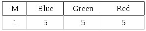
This means each color has a value of 0-31. The MSB of a pixel (M) is used to mask the pixel.
24-bit direct display
The GPU can also be set to 24bit mode, in which case 3 bytes form one pixel, 1 byte for each color. Data in this mode is arranged as follows:
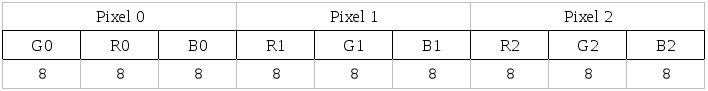
Thus 2 display pixels are encoded in 3 frame buffer pixels. They are displayed as follows: [R0,G0,B0] [R1,G1,B1].
Primitives
A basic figure which the GPU can draw is called a primitive, and it can draw the following:
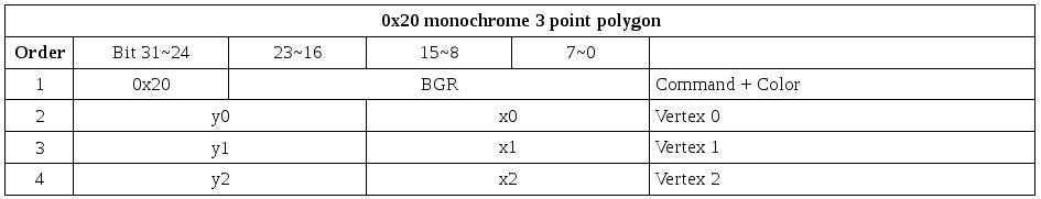
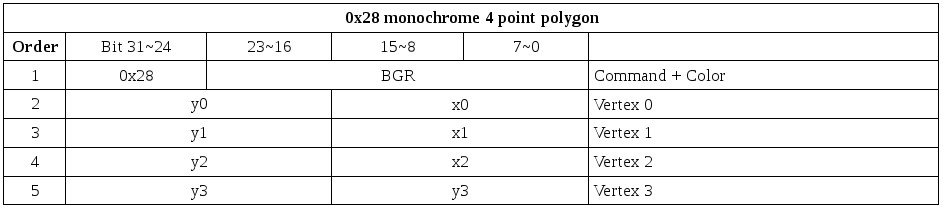
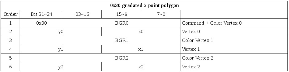
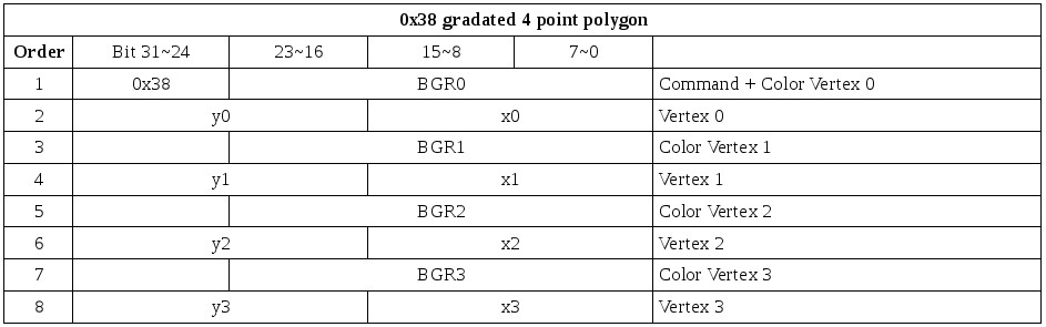
Polygon
The GPU can draw 3 point and 4 point polygons. Each point of the polygon specifies a point in the frame buffer. The polygon can be also be gourad shaded. The correct order of vertices for 4 point polygons is as follows
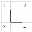
A 4 point polygon is processed internally as two 3 point polygons. also note when drawing a polygon the GPU will not draw the right most and bottom edge. So a (0,0)-(32,32) rectangle will actually be drawn as (0,0)-(31,31). Make sure adjoining polygons have the same coordinates if you want them to touch each other!
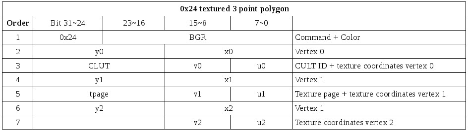
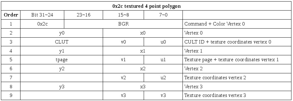
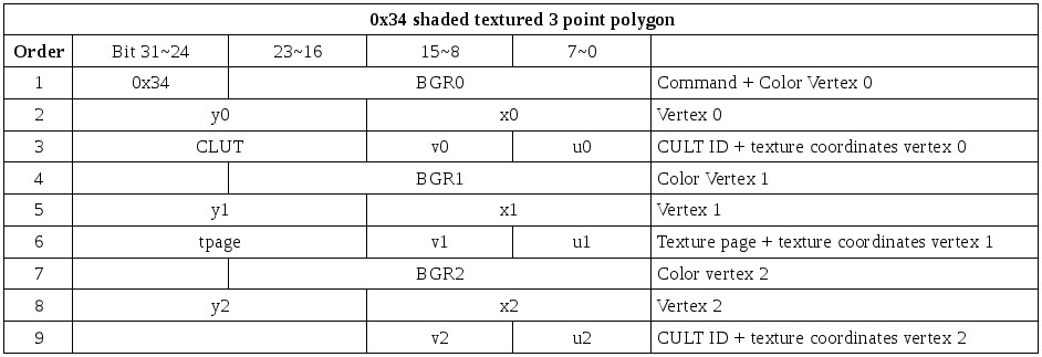
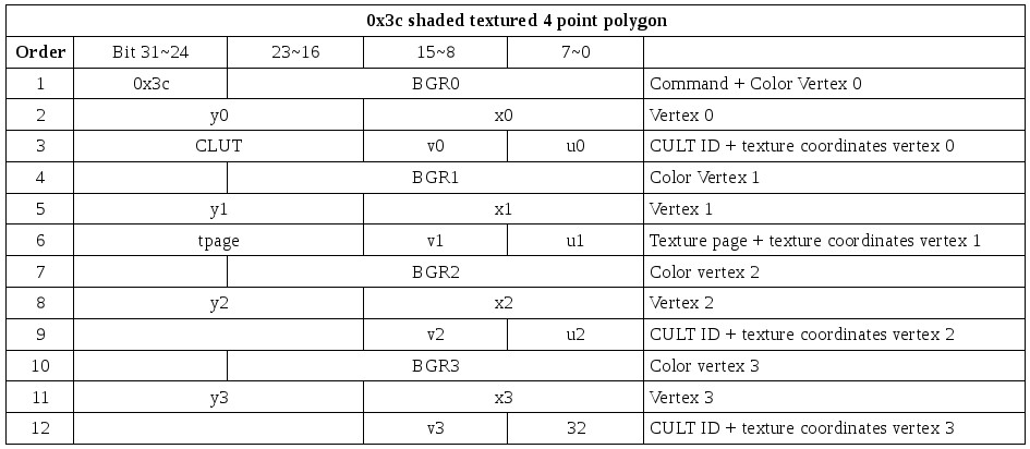
Polygon with texture
A primitive of this type is the same as above, except that a texture is applied. Each vertex of the polygon maps to a point on a texture page in the frame buffer. The polygon can be gourad shaded. Because a 4 point polygon is processed internally as two 3 point polygons, texture mapping is also done independently for both halves. This has some annoying consequences.
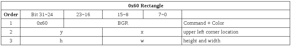
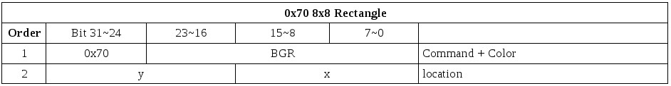
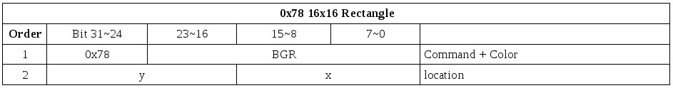
Rectangle
A rectangle is defined by the location of the top left corner and its width and height. Width and height can be either free, 8*8 or 16*16. It's drawn much faster than a polygon, but gourad shading is not possible.
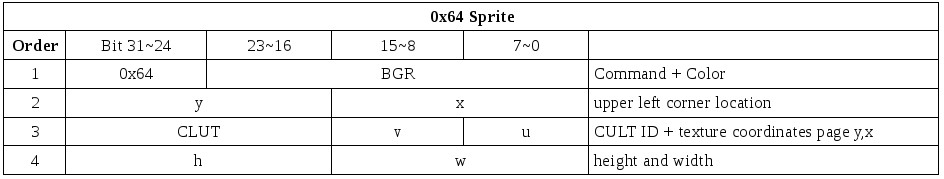
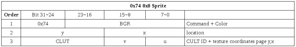
Sprite
A sprite is a textured rectangle, defined as a rectangle with coordinates on a texture page. Like the rectangle is drawn much faster than the polygon equivalent. No gourad shading possible. Even though the primitive is called a sprite, it has nothing in common with the traditional sprite, other than that it's a rectangular piece of graphics. Unlike the PSX sprite, the traditional sprite is NOT drawn to the bitmap, but gets sent to the screen instead of the actual graphics data at that location at display time.
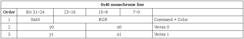
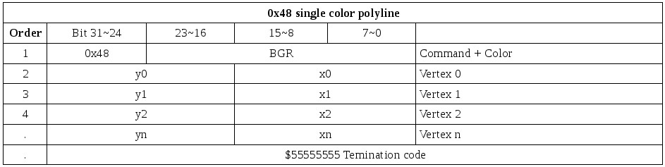
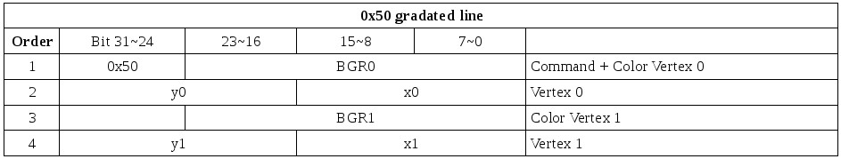
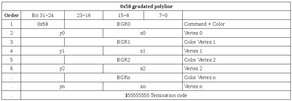
Line
A line is a straight line between 2 specified points. The line can be gourad shaded. A special form is the polyline, for which an arbitrary number of points can be specified.
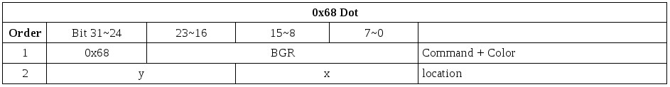
Dot
The dot primitive draws one pixel at the specified coordinate and in the specified color. It is actually a special form of rectangle, with a size of 1x1.
Textures
A texture is an image put on a polygon or sprite. It is necessary to prepare the data beforehand in the frame buffer. This image is called a texture pattern. The texture pattern is located on a texture page which has a standard size and is located somewhere in the frame buffer, see below. The data of a texture can be stored in 3 different modes
15-bit direct mode
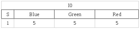
This means each color has a value of 0-31. The MSB of a pixel (S) is used to specify it the pixel is semi transparent or not. More on that later.
8bit CLUT mode
Each pixel is defined by 8bits and the value of the pixel is converted to a 15-bit color using the CLUT(color lookup table) much like standard VGA pictures. So in effect you have 256 colors which are in 15bit precision.
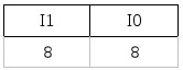
I0 is the index to the CLUT for the left pixel, I1 for the right.
4-bit CLUT mode
Same as above except that only 16 colors can be used. Data is arranged as follows:
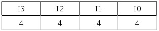
I0 is first drawn to the left to I3 to the right.
Texture Pages
Texture pages have a unit size of 256*256 pixels, regardless of color mode. This means that in the frame buffer they will be 64 pixels wide for 4bit CLUT, 128 pixels wide for 8bit CLUT and 256 pixels wide for 15-bit direct. The pixels are addressed with coordinates relative to the location of the texture page, not the frame buffer. So the top left texture coordinate on a texture page is (0,0) and the bottom right one is (255,255). The pages can be located in the frame buffer on X multiples of 64 and Y multiples of 256. More than one texture page can be set up, but each primitive can only contain texture from one page.
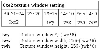
Texture Windows
The area within a texture window is repeated throughout the texture page. The data is not actually stored all over the texture page but the GPU reads the repeated patterns as if they were there. The X and Y and H and W must be multiples of 8.
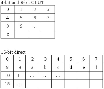
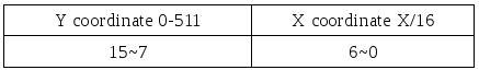
CLUT (Color Lookup Table)
The CLUT is a the table where the colors are stored for the image data in the CLUT modes. The pixels of those images are used as indexes to this table. The CLUT is arranged in the frame buffer as a 256x1 image for the 8bit CLUT mode, and a 16x1 image for the 4bit CLUT mode. Each pixel as a 16 bit value, the first 15 used of a 15 bit color, and the 16th used for semi-transparency. The CLUT data can be arranged in the frame buffer at X multiples of 16 (X=0,16,32,48,etc) and anywhere in the Y range of 0-511. More than one CLUT can be prepared but only one can be used for each primitive.
Texture Caching
If polygons with texture are displayed, the GPU needs to read these from the frame buffer. This slows down the drawing process, and as a result the number of polygons that can be drawn in a given time span. To speed up this process the GPU is equipped with a texture cache, so a given piece of texture needs not to be read multiple times in succession. The texture cache size depends on the color mode used for the textures. In 4-bit CLUT mode it has a size of 64x64, in 8-bit CLUT it's 32x64 and in 15-bit direct is 32x32. A general speed up can be achieved by setting up textures according to these sizes. For further speed gain a more precise knowledge of how the cache works is necessary.
Cache blocks
The texture page is divided into non-overlapping cache blocks, each of a unit size according to color mode. These cache blocks are tiled within the texture page.

Cache entries
Each cache block is divided into 256 cache entries, which are numbered sequentially, and are 8 bytes wide. So a cache entry holds 16 4-bit CLUT pixels 8 8-bit CULT pixels, or 4 15bitdirect pixels.
The cache can hold only one cache entry by the same number, so if for example, a piece of texture spans multiple cache blocks and it has data on entry 9 of block 1, but also on entry 9 of block 2, these cannot be in the cache at once.
Rendering options
There are 3 modes which affect the way the GPU renders the primitives to the frame buffer.
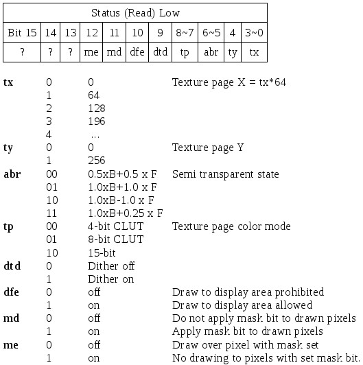
Semi Transparency
When semi transparency is set for a pixel, the GPU first reads the pixel it wants to write to, and then calculates the color it will write from the 2 pixels according to the semi-transparency mode selected. Processing speed is lower in this mode because additional reading and calculating are necessary. There are 4 semi-transparency modes in the GPU.
F=the half transparent pixel
B=the pixel read from the image in the frame buffer
1.0 x B + 0.50 x F
1.0 x B + 1.00 x F
1.0 x B - 1.00 x F
1.0 x B + 0.25 x F
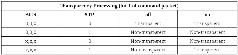
A new semi transparency mode can be set for each primitive. For primitives without texture semi- transparency can be selected. For primitives with texture semi transparency is stored in the MSB of each pixel, so some pixels can be set to STP others can be drawn opaque. For the CLUT modes the STP bit is obtained from the CLUT. So if a color index points to a color in the CLUT with the MSB set, it will be drawn semi transparent.
When the color is black(BGR=0), STP is processed different from when it's not black (BGR != 0). The table below shows the differences:
Shading
The GPU has a shading function, which will scale the color of a primitive to a specified brightness. There are 2 shading modes: Flat shading, and gourad shading. Flat shading is the mode in which one brightness value is specified for the entire primitive. In gourad shading mode, a different brightness value can be given for each vertex of a primitive, and the brightness between these points is automatically interpolated.
Mask
The mask function will prevent to GPU to write to specific pixels when drawing in the frame buffer. This means that when the GPU is drawing a primitive to a masked area, it will first read the pixel at the coordinate it wants to write to, check if it's masking bit is set, and if so refrain from writing to that particular pixel. The masking bit is the MSB of the pixel, just like the STP bit. To set this masking bit, the GPU provides a mask out mode, which will set the MSB of any pixel it writes. If both mask out and mask evaluation are on, the GPU will not draw to pixels with set MSB's, and will draw pixels with set MSB's to the others, these in turn becoming masked pixels.
Drawing Environment
The drawing environment specifies all global parameters the GPU needs for drawing primitives.
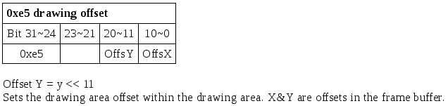
Drawing offset
This locates the top left corner of the drawing area. Coordinates of primitives originate to this point. So if the drawing offset is (0, 240) and a vertex of a polygon is located at (16, 20) it will be drawn to the frame buffer at (0+16, 240+20).
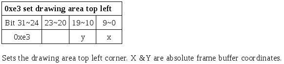
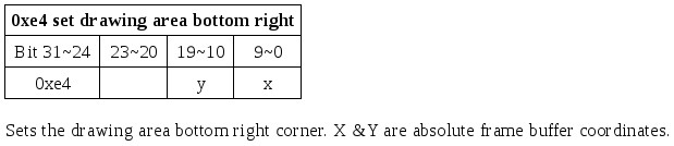
Drawing clip area
This specifies the maximum range the GPU draws primitives to. So in effect it specifies the top left and bottom right corner of the drawing area.
Dither enable
When dither is enabled the GPU will dither areas during shading. It will process internally in 24 bit and dither the colors when converting back to 15-bit. When it is off, the lower 3 bits of each color simply get discarded.
Draw to display enable
This will enable/disable any drawing to the area that is currently displayed.
Mask enable
When turned on any pixel drawn to the frame buffer by the GPU will have a set masking bit. (= set MSB)
Mask judgement enable
Specifies if the mask data from the frame buffer is evaluated at the time of drawing.
Display Environment
This contains all information about the display, and the area displayed.
Display area in frame buffer
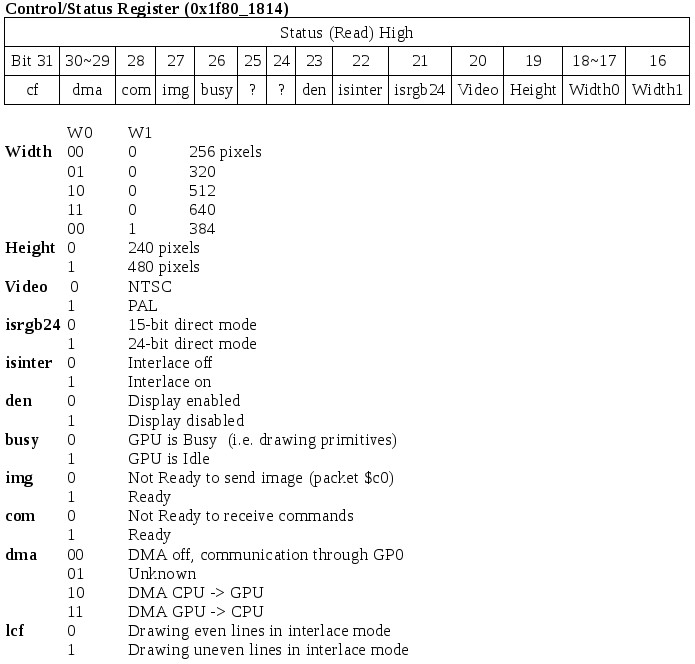
This specifies the resolution of the display. The size can be set as follows:
Width: 256, 320, 384, 512 or 640 pixels
Height: 240 or 480 pixels
These sizes are only an indication on how many pixels will be displayed using a default start end. These settings only specify the resolution of the display.
Display start/end
Specifies where the display area is positioned on the screen, and how much data gets sent to the screen. The screen sizes of the display area are valid only if the horizontal/vertical start/end values are default. By changing these you can get bigger/smaller display screens. On most TV's there is some black around the edge, which can be utilized by setting the start of the screen earlier and the end later. The size of the pixels is NOT changed with these settings, the GPU simply sends more data to the screen. Some monitors/TVs have a smaller display area and the extended size might not be visible on those sets.(Mine is capable of about 330 pixels horizontal, and 272 vertical in 320x240 mode)
Interlace enable
When enabled the GPU will display the even and odd lines of the display area alternately. It is necessary to set this when using 480 lines as the number of scan lines on a TV screen are not sufficient to display 480 lines.
15bit/24bit direct display
Switches between 15bit/24bit display mode.
Video mode
Selects which video mode to use, which are either PAL or NTSC.
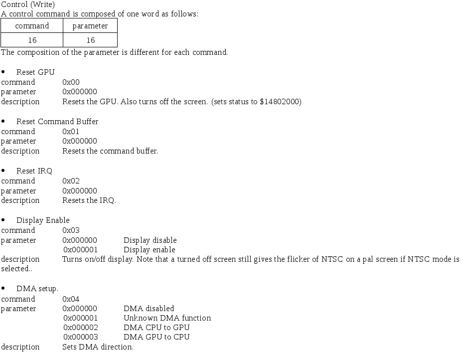
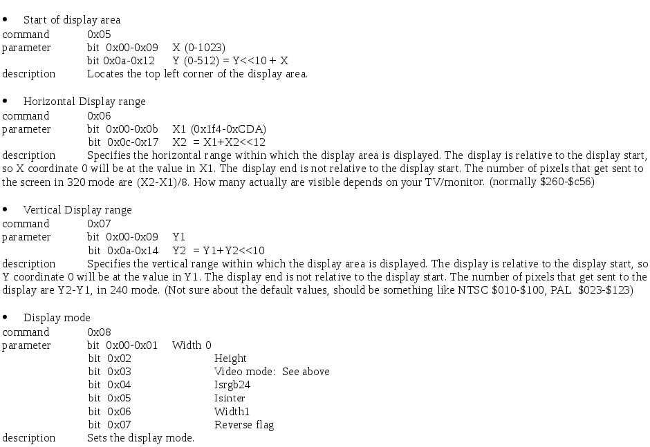
GPU operation
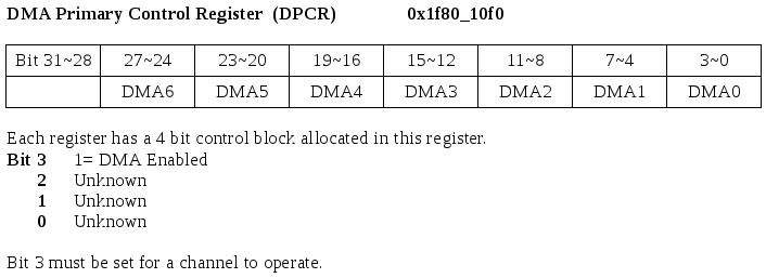
GPU control registers
There are 2 32 bit IO ports for the GPU, which are at 0x1f80_1810 for GPU Data and 0x1f80_1814 for GPU control/Status. The data register is used to exchange data with the GPU and the control/status register gives the status of the GPU when read, and sets the control bits when written to.
Command Packets, Data Register
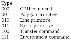
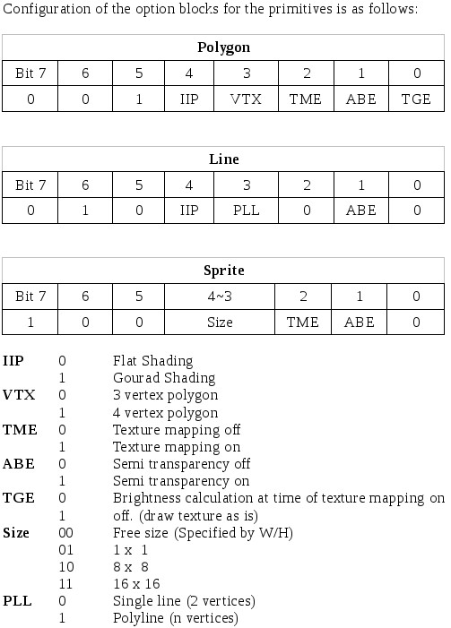
Primitive command packets use an 8 bit command value which is present in all packets. They contain a 3 bit type block and a 5 bit option block of which the meaning of the bits depend on the type. layout is as follows:
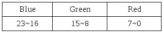
Color information
Color information is forwarded as 24-bit data. It is parsed to 15-bit by the GPU.
Layout as follows:
Shading information
For textured primitive shading data is forwarded by this packet. Layout is the same as for color data, the RGB values controlling the brightness of the individual colors ($00-$7f). A value of $80 in a color will take the former value as data.
Texture Page information
The Data is 16 bit wide, layout is as follows:
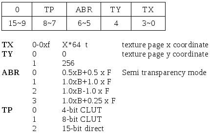
CLUT-ID
Specifies the location of the CLUT data. Data is 16-bits.
Abbreviations in packet list
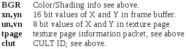
Packet list
The packets sent to the GPU are processed as a group of data, each one word wide. The data must be written to the GPU data register ($1f801810) sequentially. Once all data has been received, the GPU starts operation.
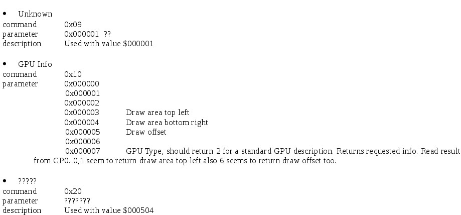
Overview of packet commands
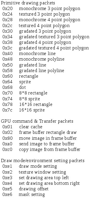
Packet Descriptions
Primitive Packets

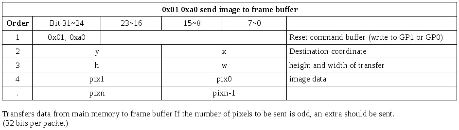
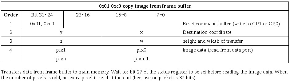
GPU command & Transfer packets
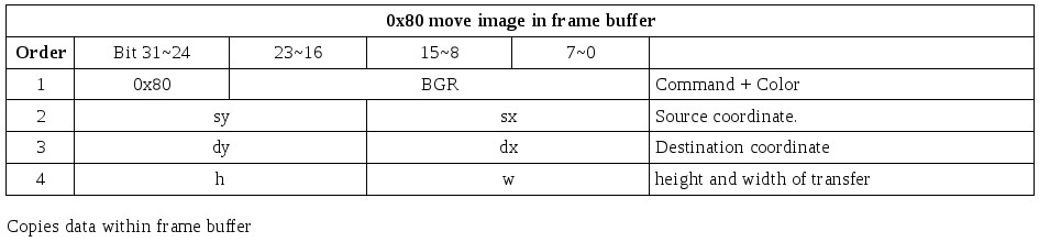
Draw mode/environment setting packets
Some of these packets can also be by primitive packets, in any case it is the last packet of either that the GPU received that is active. so if a primitive sets tpage info, it will over write the existing data, even if it was sent by an 0xe? packet.
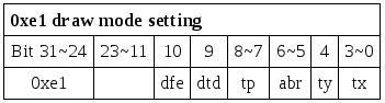
See above for explanations
It seems that bits 11-13 of the status register can also be passed with this command on some GPU's other than type 2. (i.e. Command 0x10000007 doesn't return 2)
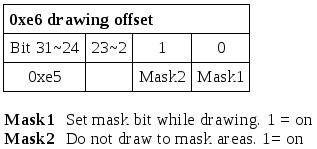
While mask1 is on, the GPU will set the MSB of all pixels it draws. While mask2 is on, the GPU will not write to pixels with set MSB's
DMA and the GPU
The GPU has two DMA channels allocated to it. DMA channel 2 is used to send linked packet lists to the GPU and to transfer image data to and from the frame buffer. DMA channel 6 is sets up an empty linked list, of which each entry points to the previous (i.e. reverse clear an OT.)
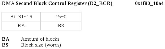
Sets up the DMA blocks. Once started the DMA will send BA blocks of BS
words. Don't set a block size larger then $10 words, as the command buffer
of the GPU is 64 bytes.
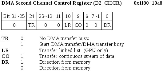
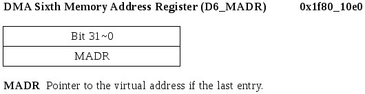
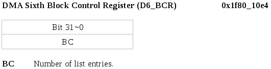
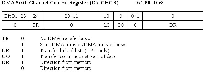
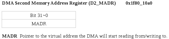
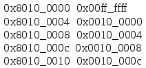
This configures the DMA channel. The DMA starts when bit 18 is set. DMA is finished as soon as bit 18 is cleared again. To send or receive data to/from VRAM send the appropriate GPU packets first (0xa0/0xc0) When this register is set to $11000002, the DMA channel will create an empty linked list of D6_BCR entries ending at the address in D6_MADR. Each entry has a size of 0, and points to the previous. The first entry is So if D6_MADR = $80100010, D6_BCR=$00000004, and the DMA is kicked this mwill result in a list looking like this:
Common GPU functions, step by step
Initializing the GPU
First thing to do when using the GPU is to initialize it. To do that take the following steps:
1 - Reset the GPU (GP1 command $00). This turns off the display as well.
2 - Set horizontal and vertical start/end. (GP1 command $06, $07)
3 - Set display mode. (GP1 command $08)
4 - Set display offset. (GP1 command $05)
5 - Set draw mode. (GP0 command $e1)
6 - Set draw area. (GP0 command $e3, $e4)
7 - Set draw offset. (GP0 command $e5)
8 - Enable display.
Sending a linked list
The normal way to send large numbers of primitives is by using a linked list DMA transfer. This list is built up of entries of which each points to the next. One entry looks like this:
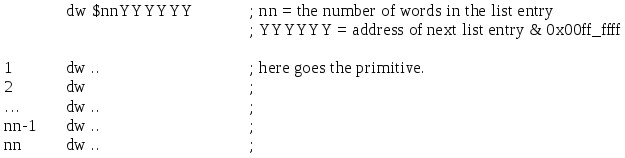
The last entry in the list should have 0xffffff as pointer, which is the terminator. As soon as this value is found DMA is ended. If the entry size is set to 0, no data will be transferred to the GPU and the next entry is processed.
To send the list do this:
1 - Wait for the GPU to be ready to receive commands. (bit $1c == 1)
2 - Enable DMA channel 2
3 - Set GPU to DMA CPU->GPU mode. ($04000002)
3 - Set D2_MADR to the start of the list
4 - Set D2_BCR to zero.
5 - Set D2_CHCR to link mode, memory->GPU and DMA enable. ($01000401)
Uploading Image data through DMA
To upload an image to VRAM take the following steps:
1 - Wait for the GPU to be idle and DMA to finish. Enable DMA channel 2 if necessary.
2 - Send the 'Send image to VRAM' primitive. (You can send this through DMA if you want. Use the linked list method described above)
3 - Set DMA to CPU->GPU ($04000002) (if you didn't do so already in the previous step)
4 - Set D2_MADR to the start of the list
5 - Set D2_BCR with:
bits 31-16 = Number of words to send (H*W /2)
bits 15- 0 = Block size of 1 word. ($01)
if H*W is odd, add 1. (Pixels are 2 bytes, send an extra blank pixel in case of an odd amount)
6 - Set D2_CHCR to continuous mode, memory -> GPU and DMA enable. ($01000201)
Note that H, W, X and Y are always in frame buffer pixels, even if you send image data in other formats.
You can use bigger block sizes if you need more speed. If the number of words to be sent is not a multiple of the block size, you'll have to send the remainder separately, because the GPU only accepts an extra halfword if the number of pixels is odd. (i.e. of the last word sent, only the low half word is used.) Also take care not to use block sizes bigger than 0x10, as the buffer of the GPU is only 64 bytes (=0x10 words).
Waiting to send commands
You can send new commands as soon as DMA has ceased and the GPU is ready.
1 - Wait for bit $18 to become 0 in D2_CHCR
2 - Wait for bit $1c to become 1 in GP1.