Linux Device Driver >> Assembly (ARM)
gpio output
參考資訊:
1. ldd
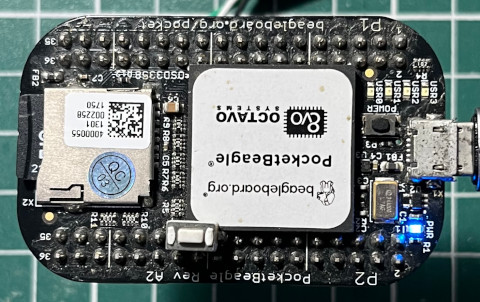
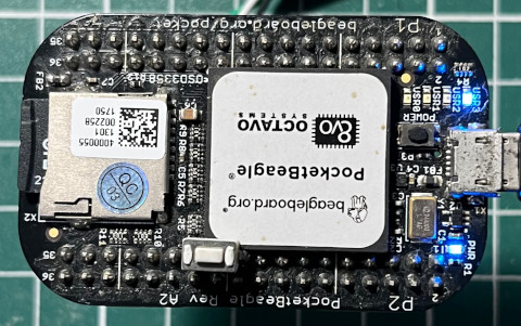
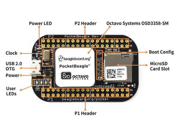
PocketBeagle開發板上有四顆USR LED,此次範例將使用USR3 LED,位置如下:
Device Tree(arch/arm/boot/dts/am335x-pocketbeagle-common.dtsi)
led@5 {
    label = "beaglebone:green:usr3";
    gpios = <&gpio1 24 GPIO_ACTIVE_HIGH>
    linux,default-trigger = "mmc1";
    default-state = "off";
};
P.S. USR3位置是GPIO1-24
Linux驅動程式可以當作是在寫韌體程式,因此,可以在驅動程式裡面直接操作GPIO暫存器,當然也可以遵循Linux Kernel規範,使用統一的GPIO操作函數,如果GPIO驅動程式沒有先移植好的話,那就只能使用暫存器的操作方式,幸運地,在這一版PocketBeagle Kernel中,已經完成GPIO驅動程式的移植,因此,此範例將使用Linux Kernel統一的GPIO操作函數
使用步驟如下:
1. gpio_request()
2. gpio_to_desc()
3. gpiod_direction_output_raw()
4. gpiod_set_raw_value()
5. gpio_free()
ldd.S
    .global init_module
    .global cleanup_module

    .equ USR3_LED, ((32 * 1) + 24)

    .section .modinfo, "ae"
__UNIQUE_ID_0: .asciz "license=GPL"
__UNIQUE_ID_1: .asciz "author=Steward Fu"
__UNIQUE_ID_2: .asciz "description=Linux Driver"

    .section .text
led_name: .asciz "USR3"

    .align 2
    .section .text
init_module:
    push {r4, r5, lr}

    mov r0, #USR3_LED
    ldr r1, =led_name
    bl gpio_request

    mov r0, #USR3_LED
    bl gpio_to_desc
    mov r5, r0

    mov r0, r5
    mov r1, #1
    bl gpiod_direction_output_raw

    mov r4, #30
loop:
    mov r0, r5
    mov r1, #0
    bl gpiod_set_raw_value

    mov r0, #1000
    bl msleep

    mov r0, r5
    mov r1, #1
    bl gpiod_set_raw_value

    mov r0, #1000
    bl msleep

    subs r4, #1
    bne loop

    mov r0, #USR3_LED
    bl gpio_free

    mov r0, #0
    pop {r4, r5, pc}

cleanup_module:
    push {lr}
    pop {pc}
    .end
init_module: 請求GPIO資源,接著設定GPIO輸出方向,最後使用迴圈點亮LED(30次)
完成